INSTALLING & UPDATING YOUR CLARALIGHT PANEL
Box Contents & Unpacking
Exact contents and quantities will vary depending upon what has been ordered but typical contents will comprise:
• Claralight Display Panels in A3 Landscape or A4 Portrait Configuration. Do not lift the panel by one corner,
• Transformer
• Cable Kit(s)
• Transformer Power Connectors
• Fittings pack comprising Allen Key and spare Grubscrews
• Instruction Sheet
Carefully cut through the tape on the top of the box and open fully. Remove the packing sheet of cardboard on top. On one side of the box you will see a cardboard fitting containing transformer and other accessories, remove this fitting first and all parts and retain for installation. Remove the one side of the cardboard fitting holding the panels in place and carefully lift out each panel from the remaining fitting. All cardboard packaging can now be recycled.
Download this Guide here
GETTING STARTED
Installation of Panels onto Cables
THIS GUIDE RELATES TO INSTALLATION OF A3 LANDSCAPE OR A4 PORTRAIT PANELS, TO USE EITHER IN THE OTHER ORIENTATION PLEASE REFER TO THE CHANGING PANEL ORIENTATION SECTION PRIOR TO COMMENCING INSTALLATION. ALL LIGHT PANELS SHOULD BE INSTALLED A MINIMUM OF 300MM AWAY FROM THE WINDOW PANE
Ensure cables are installed safely into ceiling and floor and have the correct cable centre dimensions to match the panel size & orientation you require.
Panel Size & Orientation | Cable Centres |
A3 Landscape 446.4mm w x 323.4mm h | 450mm |
A3 Portrait 323.4mm w x 446.4mm h | 327mm |
A4 Landscape 323.4mm w x 236.4mm h | 327mm |
A4 Portrait 236.4 mm w x 323.4mm h | 240mm |
NEVER LIFT THE PANEL BY ONE CORNER
The Claralight panel has four plastic clips protruding from the longest sides, you will notice one face of these has a hexagon pattern, this is the window facing side of the panel which is the one referred to in this guide.
With this window facing side towards you lay down one panel and carefully remove the magnetic lens. In two of the corners on the panel underneath you will see Positive (+) and Negative (-) symbols, the panel needs to be orientated so that these match the polarity of the transformer leads on the installed cables. Once you have established the panel is orientated correctly, carefully replace the magnetic lens. Next, offer the complete panel up to the cables and starting with the upper right clip, using the Allen key provided remove the small grubscrew and retain. Thread the cable through the groove in the clip and ensure it locates under the top and bottom bumps. Re-fit the grubscrew to fully secure the panel. Repeat this process for the bottom left clip, then finally for the remaining two clips, note the two remaining clips will not be supplied with or require grubscrews. Switch on the transformer to confirm the panel illuminates. The panel can be raised or lowered to the desired position, use a spirit level for best results. Once the panel is in its final position secure by inserting a supplied grubscrew into the top right and bottom left clips, use the provided Allen Key to tighten. DO not overtighten, stop once resistance is felt. Repeat to install the remaining panels.
Once panels are in position remove the protective film covering from the front of the lenses. To do this pull the lens away from the panel to remove it, then using the finger lift tab slowly and carefully pull and the film will detach from the panel. Place the lens back onto the panel and the magnets will hold in place, taking care not to touch the inner panel itself. Repeat with the other face of the panel and then all other panels.
Adding and Changing of Graphics
Remove lens from panel as described above. Place the lens face down on a protective surface (magnetic edges will be face up) Insert your required graphic into the aperture on the lens using the magnetic tape edges to locate correctly. Lift up the lens whilst ensuring the graphic stays in place and place back onto the panel. Repeat for the other panel face
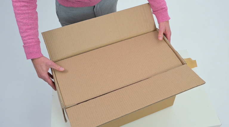
UNBOXING
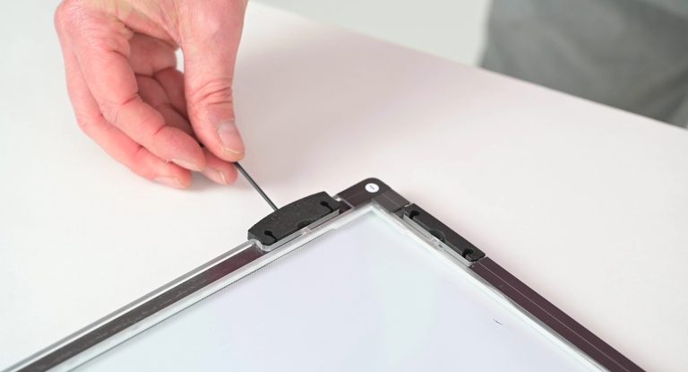
REMOVING THE GRUB SCREW
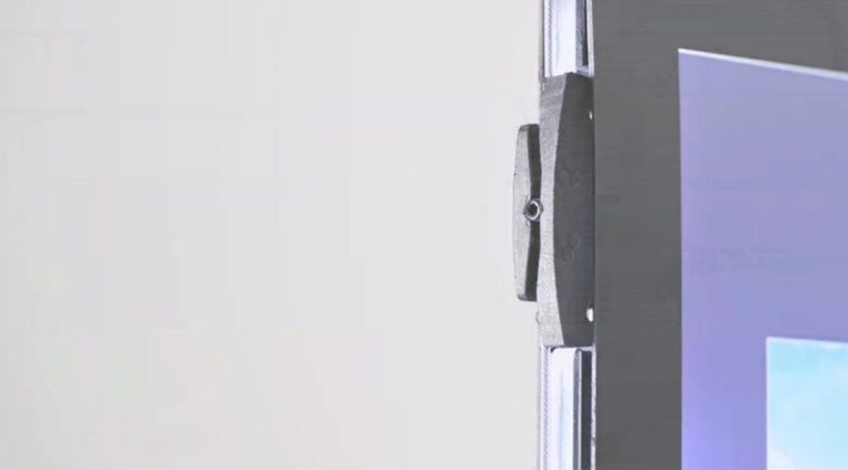
TIGHTENING THE GRUB SCREW
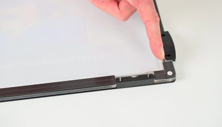
IDENTIFYING THE POLARITY
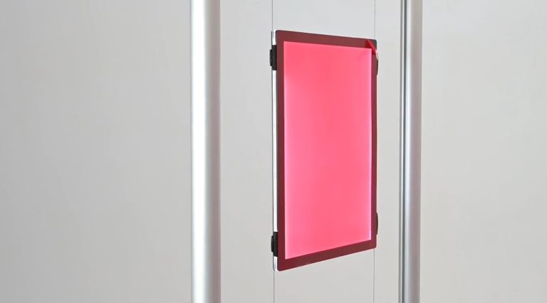
CLIPPING PANEL ONTO CABLE
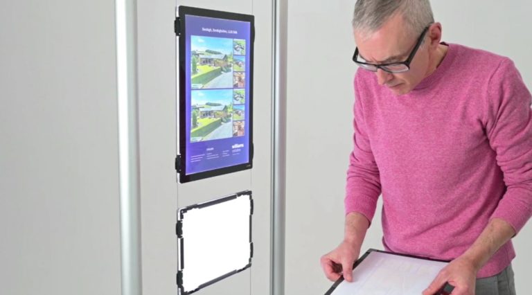
INSERTING A GRAPHIC
CHANGING ORIENTATION
Panels are supplied in Landscape format for A3 and Portrait format for A4 by default, but the orientation can be easily changed if required. To do this, first remove the panel from the cables by removing the grubscrews from the two clips that have them (retain these safely for later) and then unlinking the cable from the clips whilst holding the panel securely. Remove magnetic lenses from both sides of the panel and safely put to one side. Place the inner panel down with the hexagons on the clips facing upwards, onto a protective, soft surface to prevent damage. During the next stages it is important to not touch the light grid area of the inner panel with your fingers at any time as fingerprints will become visible when the panel is illuminated. Always ensure the hexagons are facing upwards before attempting this as irreparable damage may occur to the panel if not.
You will see a small semi circular recess where the clip meets the panel, using a medium flat headed screwdriver carefully insert it into this recess and twist to gently prise the clip away from the panel. Do not use excessive force as this may cause damage to the panel. Do the same for all remaining clips and blanking plates around the edge of the panel. You will notice that two of the clips have a metal pin protruding from them and two do not, when replacing the clips in the new orientation it is essential that the ones with the metal pin are placed in the correct positions. Turn the panel so that it is the correct orientation and look at the edge of the panel to identify the two positions that have a metal clip inside. These will need to be the positions used for the clips with metal pins. Begin with these by locating one edge of the clip into the recess on the panel and click the other edge into place. If significant resistance is felt then tap in with a rubber mallet or similar being careful not to exert excessive force to cause damage. Insert the two remaining clips into the remaining positions on these edges and then follow on with the blanking clips being fitted to the recesses in the opposite edges. The lenses can then be added to the front and back and the panel can be clipped back onto the cables. Screw the two grubscrews back in at the positions with the metal pin. Repeat for any further panels requiring orientation change.
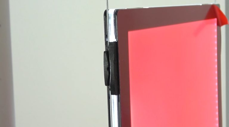
UNCLIPPING THE PANEL
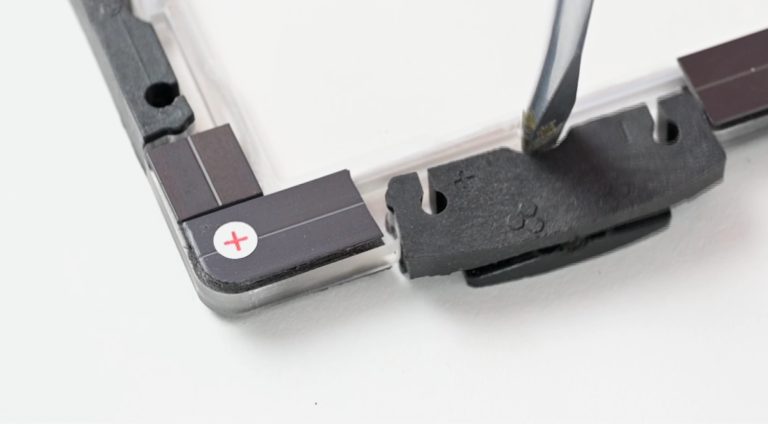
CHANGING ORIENTATION
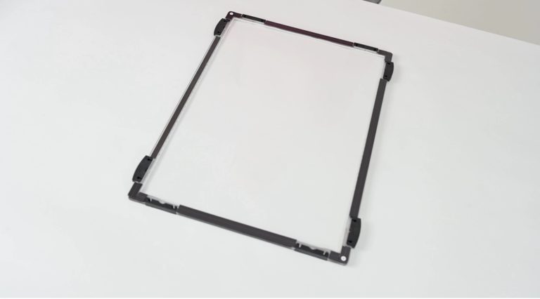
DO NOT TOUCH
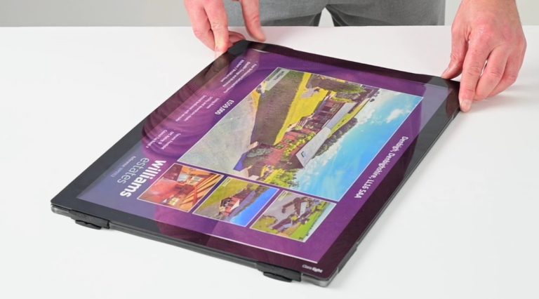
CHANGING THE GRAPHIC
Troubleshooting
- Panel Not Illuminating
- Check grubscrew is pushing cable fully into clip
- Check panel has been fitted to cables with correct polarity (+ on inner panel is on the same cable as the transformer + output)
- Ensure correct 24V transformer is being used
- If panel orientation has been changed, ensure clips with pins are located onto the apertures with visible metal plate
Maintenance and Care
- To clean lenses wipe gently with a soft cloth, under no circumstances use any chemical or abrasives on the unit
- Always leave graphic prints to air dry for 24 hours prior to fitting them into the panel as inks may still be wet and may stick to the inside of the lens
- Check cable tension and tighten grubscrews once a month
- Do not clean or touch the inner panel with bare hands
